Dear Web User:
For Better View Of This Web Page, Please Use Any Latest Web Browser, Because Some Elements Are Not Work In The Old Web Browser (It Might Not Be Displayed Properly Or Are Not Appearing properly!).Plz Note:
Some Topics That You Might Want To Pursue On Your Own That We Did Not Cover In This Article Are Listed Here. This Page Discusses “INITIAL CONFIGURATION REFERENCES OF CISCO ROUTERS AND SWITCHES”, And Also We Request To The Students, Please Go Through All The Articles That Are We Posted In This Web Site And Also Identify All The CISCO IOS Commands In The Lab Practice Before Going To Access This Page. Experience Is The Sequence Of Hands-On LABs. Thank You!FOR MORE REFERENCES:
◙ - ➤ For More Reference - > KEYBOARD SHORTCUTS (MICROSOFT WINDOWS):
◙ - ➤ For More Reference - > KEYBOARD SHORTCUTS REFERENCE FOR CISCO IOS;
◙ - ➤ For More Reference - > BASIC COLLECTION OF NETWORKING CONCEPTS:
◙ - ➤ For More Reference- > RIP CONFIGURATION EXAMPLES:
◙ - ➤ For More Reference - > STATIC ROUTES Vs DYNAMIC ROUTES:
◙ - ➤ For More Reference - > BASIC NETWORKING QUESTIONS AND ANSWER:
◙ - ➤ For More Reference- > IP ROUTING QUESTIONS AND ANSWERS:
BASIC TROUBLESHOOTING COMMANDS
TROUBLESHOOTING ISSUES (THESE COMMANDS CAN BE USED TO PERFORM TROUBLESHOOTING): Connectivity Can Be Tested With Several Other Commands SUCH AS: PING, TRACEROUTE, And SHOW IP ROUTE.
◙ - ➤ TESTING THE LOOPBACK: As A First Step In The Testing Sequence, The Ping Command Is Used To Verify The Internal IP Configuration On The Local Host. Recall That This Test Is Accomplished By Using The Ping Command On A Reserved Address Called The Loopback (127.0.0.1). This Verifies The Proper Operation Of The Protocol Stack From The Network Layer To The Physical Layer - And Back - Without Actually Putting A Signal On The Media. PING COMMANDS ARE ENTERED INTO A COMMAND LINE (Enter The Pingloopback Command With This Syntax: C:\>Ping 127.0.0.1 THE REPLY FROM THIS COMMAND WOULD LOOK SOMETHING LIKE THIS: Reply From 127.0.0.1: Bytes=32 Time<1ms TTL=128Reply From 127.0.0.1: Bytes=32 Time<1ms TTL=128
Reply From 127.0.0.1: Bytes=32 Time<1ms TTL=128
Reply From 127.0.0.1: Bytes=32 Time<1ms TTL=128 Ping Statistics For 127.0.0.1:
Packets: Sent = 4, Received = 4, Lost = 0 (0% Loss), Approximate Round Trip Times In Milli-Seconds:
Minimum = 0ms, Maximum = 0ms, Average = 0ms The Result Indicates That Four Test Packets Were Sent - Each 32 Bytes In Size - And Were Returned From Host 127.0.0.1 In A Time Of Less Than 1 Ms. TTL Stands For Time To Live And Defines The Number Of Hops That The Ping Packet Has Remaining Before It Will Be Dropped. ◙ - ➤ TELNET: Verifies The Application Layer Software Between The Source And The Destination. This Is The Most Complete Test Mechanism Available. Telnet Provides Network Administrators With Remote Connection Capability. ◙ - ➤ PING: Uses The ICMP Protocol To Verify The Hardware Connection And The IP Address Of The Network Layer. This Is A Very Basic Test Mechanism. The Ping Command Uses ICMP To Send An Echo Request To A Destination And Then Awaits An Echo Reply From That Destination. FOR THE PING COMMAND FORMAT: Router>Ping IP Address Example With Values: Router>ping 10.10.10.5 The Command Is Ping And The Argument Is The IP Address. ◙ - ➤ TRACEROUTE: Is Used To Find Failures In The Path From The Source To Destination. Traceroute Uses Time-To-Live Values To Generate Messages From Each Router Along The Path. Troubleshooting Is One Of The Most Important Skills Of A Network Associate. THE TRACEROUTE COMMAND FORMATIS: Switch>Traceroute IP Address Example With Values: Switch>Traceroute 192.168.254.254 The Command Is Traceroute And The Argument Is The IP Address. Commands Are Used To Execute An Action, And The Keywords Are Used To Identify Where Or How To Execute The Command.
◙ - ➤ For More Reference - > USEFUL NETWORKING DOS COMMAND REFERENCE:
◙ - ➤ SHOW IP ROUTE: Command Is Used To Identify The Routes That Are Shown In The Routing Table. These Are Routes To Directly Connected Networks, Networks With Static Routes, Or Networks That Have Been Learned Through A Routing Protocol. ◙ - ➤ SHOW command : The Keywords Describe Specific Parameters To The Command Interpreter. For Example, The Show Command Is Used To Display Information About The Device. This Command Has Various Keywords That Can Be Used To Define What Particular Output Should Be Displayed. For Example: Switch#Show Running-Config The Command Show Is Followed By The Keyword Running-Config. The Keyword Specifies That The Running Configuration Is To Be Displayed As The Output.◙ - ➤ For More Reference - > LIST OF SHOW COMMAND REFERENCES:
◙ - ➤ For More Reference - > LIST OF IPv6 COMMAND REFERENCES:
TYPE OF CABLES TO USE BETWEEN HUBS, SWITCHES, ROUTERS

CROSSOVER Vs STRAIGHT-THROUGH CABLES
CROSSOVER VERSUS STRAIGHT-THROUGH:
◙ STRAIGHT-THROUGH CABLE: Four-Pair, Eight-Wire, Straight-Through Cable, Which Means That The Color Of Wire On Pin 1 On One End Of The Cable Is The Same As That Of Pin 1 On The Other End. Pin 2 Is The Same As Pin 2, And So On. The Cable Is Wired To Either EIA/TIA T568B Or T568A Standards For 10BASE-T Ethernet, Which Determines What Color Wire Is On Each Pin.

STRAIGHT-THROUGH CABLES ARE USED FOR:
◙ - ➤ SWITCH-TO-ROUTER◙ - ➤ SWITCH-TO-PC
◙ - ➤ HUB-TO-PC
◙ - ➤ HUB-TO-SERVER

CROSSOVER CABLES ARE USED FOR:
◙ - ➤ SWITCH-TO-SWITCH◙ - ➤ PC-TO-PC
◙ - ➤ SWITCH-TO-HUB
◙ - ➤ HUB-TO-HUB
◙ - ➤ ROUTER-TO-ROUTER
◙ - ➤ ROUTER-TO-SERVER Routers Support The Smart Serial Interface That Allows For More Data To Be Forwarded Across Fewer Cable Pins. The Serial End Of The Smart Serial Cable Is A 26-Pin Connector. It Is Much Smaller Than The DB-60 Connector Used To Connect To A Five-In-One Serial Port. These Transition Cables Support The Same Five Serial Standards And Are Available In Either DTE Or DCE Configurations.
◙ - ➤ For More Reference - > DTE Vs DCE:
ETHERNET CONNECTORS ARE USED FOR:
A Different Connector Is Used In An Ethernet-Based LAN Environment. An RJ-45 Connector For The Unshielded Twisted-Pair (UTP) Cable Is The Most Common Connector Used To Connect LAN Interfaces. At Each End Of An RJ-45 Cable, You Should Be Able To See Eight Colored Strips, Or Pins. An Ethernet Cable Uses Pins 1, 2, 3, And 6 For Transmitting And Receiving Data. ROLLOVER CABLE - A 4-Pair "Rollover" Cable. This Type Of Cable Is Typically 3.05 M Long But Can Be As Long As 7.62 M. A Rollover Cable Can Be Used To Connect A Host Or Dumb Terminal To The Console Port On The Back Of A Router Or Switch. Both Ends Of The Cable Have RJ-45 Connectors On Them. One End Plugs Directly Into The RJ-45 Console Management Port On The Back Of The Router Or Switch. Plug The Other End Into An RJ-45-To-DB9 Terminal Adapter. This Adapter Converts The RJ-45 To A 9-Pin Female D Connector For Attachment To The PC Or Dumb Terminal Serial (COM) Port. A DB25 Terminal Adapter Is Also Available To Connect With A PC Or Dumb Terminal. This Adapter Uses A 25 Pin Connector.HOW TO CONNECT TO A CISCO STANDARD CONSOLE PORT (RJ-45):

2. Connect The RJ-45 Roll-Over Cable (Black Or Light Blue) Into The RJ-45 To DB-9 Adapter .
3. Connect The Other End Of The RJ-45 Roll-Over Cable Into Cisco Device’s Console Port.

CISCO IOS - HOT KEYS AND SHORTCUTS
HOT KEYS AND SHORTCUTS:
The CISCO IOS CLI Provides Hot Keys And Shortcuts That Make Configuring, Monitoring, And Troubleshooting Easier. MOST OF THE SHORTCUTS ARE: ◙ - ➤ Tab - > Completes The Remainder Of The Command Or Keyword Tab - Tab Complete Is Used To Complete The Remainder Of Abbreviated Commands And Parameters If The Abbreviation Contains Enough Letters To Be Different From Any Other Currently Available Commands Or Parameters. When Enough Of The Command Or Keyword Has Been Entered To Appear Unique, Press The Tab Key And The Cli Will Display The Rest Of The Command Or Keyword. This Is A Good Technique To Use When You Are Learning Because It Allows You To See The Full Word Used For The Command Or Keyword. ◙ - ➤ Ctrl-R - > Redisplays A Line Ctrl-R - Redisplay Line Will Refresh The Line Just Typed. Use Ctrl-R To Redisplay The Line. For Example, You May Find That The Ios Is Returning A Message To The Cli Just As You Are Typing A Line. You Can Use Ctrl-R To Refresh The Line And Avoid Having To Retype It. In This Example, A Message Regarding A Failed Interface Is Returned In The Middle Of A Command. Switch#Show Mac- 16w4d: %Link-5-Changed: Interface Fastethernet0/10, Changed State To Down 16w4d: %Lineproto-5-Updown: Line Protocol On Interface Fastethernet0/10, Changed State To Down To Redisplay To Line That You Were Typing Use Ctrl-R: Switch#Show Mac ◙ - ➤ Ctrl-Z - > Exits Configuration Mode And Returns To The Exec Ctrl-Z - Exit Configuration Mode. To Leave A Configuration Mode And Return To Privileged Exec Mode, Use Ctrl-Z. Because The Ios Has A Hierarchal Mode Structure, You May Find Yourself Several Levels Down. Rather Than Exit Each Mode Individually, Use Ctrl-Z To Return Directly To The Privileged Exec Prompt At The Top Level. ◙ - ➤ Down Arrow - > Allows User To Scroll Forward Through Former Commands ◙ - ➤ Up Arrow - > Allows User To Scroll Backward Through Former Commands. Up And Down Arrows - Using Previous Commands. The Cisco Ios Software Buffers Several Past Commands And Characters So That Entries Can Be Recalled. The Buffer Is Useful For Reentering Commands Without Retyping. Key Sequences Are Available To Scroll Through These Buffered Commands. Use The Up Arrow Key (Ctrl P) To Display The Previously Entered Commands. Each Time This Key Is Pressed, The Next Successively Older Command Will Be Displayed. Use The Down Arrow Key (Ctrl N) To Scroll Forward Through The History To Display The More Recent Commands. ◙ - ➤ Ctrl-Shift-6 - > Allows The User To Interrupt An IOS Process Such As Ping Or Traceroute Ctrl-Shift-6 - Using The Escape Sequence. When An Ios Process Is Initiated From The CLI, Such As A Ping Or Traceroute, The Command Runs Until It Is Complete Or Is Interrupted. While The Process Is Running, The Cli Is Unresponsive. To Interrupt The Output And Interact With The CLI, Press Ctrl-Shift-6. ◙ - ➤ Ctrl-C - > Aborts The Current Command And Exits The Configuration Mode Ctrl-C - This Interrupts The Entry Of A Command And Exits The Configuration Mode. This Is Useful When Entering A Command You May Decide That You Wish To Cancel The Command And Exits The Configuration Mode.
ABBREVIATED COMMANDS OR KEYWORDS:
Commands And Keywords Can Be Abbreviated To The Minimum Number Of Characters That Identify A Unique Selection. For Example, The Configure Command Can Be Abbreviated To Conf Because Configure Is The Only Command That Begins With Conf. An Abbreviation Of Con Will Not Work Because More Than One Command Begins With Con. AN EXAMPLE, SHOW INTERFACES CAN BE ABBREVIATED LIKE THIS: Switch#Show Interfaces Switch#Show Int YOU CAN ABBREVIATE BOTH THE COMMAND AND THE KEYWORDS, FOR EXAMPLE: Switch#Shint◙ - ➤ ALSO For More Reference - > KEYBOARD SHORTCUTS REFERENCE FOR CISCO IOS;
INTRODUCTION OF CISCO NETWORKING
INTRODUCTION:
We Will Introduce The Basic Configuration Procedures For Cisco Network Devices. These Procedures Require The Use Of The Cisco Internetwork Operating System (IOS) And The Related Configuration Files For Intermediary Devices. Network Devices, Or Intermediary Devices, Are Used To Transport Data Across The Network And Include Switches, Routers, Wireless Access Points, And Firewalls. The Operating System On A Network Device Is Known As A Network Operating System. The Cisco Internetwork Operating System (IOS) Is A Generic Term For The Collection Of Network Operating Systems Used On Cisco Networking Devices. Cisco IOS Is Used For Most Cisco Devices Regardless Of The Type Or Size Of The Device. All End Devices And Network Devices Connected To The Internet Require An Operating System (OS) To Help Them Perform Their Function. When A Computer Is Powered On, It Loads The OS, Normally From A Disk Drive, Into RAM. The Portion Of The OS Code That Interacts Directly With The Computer Hardware Is Known As The Kernel. The Portion That Interfaces With The Applications And User Is Known As The Shell. The User Can Interact With The Shell Using Either The Command-Line Interface (CLI) Or Graphical User Interface (GUI). When Using The CLI, The User Interacts Directly With The System In A Text-Based Environment By Entering Commands On The Keyboard At A Command Prompt. The System Executes The Command, Often Providing Textual Output. The GUI Interface Allows The User To Interact With The System In An Environment That Uses Graphical Images, Multimedia, And Text. Actions Are Performed By Interacting With The Images On Screen. GUI Is More User Friendly And Requires Less Knowledge Of The Command Structure To Utilize The System. For This Reason, Many Individuals Rely On The GUI Environments. Many Operating Systems Offer Both GUI And CLI. Most End Device Operating Systems Are Accessed Using A GUI, Including MS Windows, MAC OS X, Linux, Apple IOS, Android, And More. The Operating System On Home Routers Is Usually Called Firmware. The Most Common Method For Configuring A Home Router Is Using A Web Browser To Access An Easy To Use GUI. Most Home Routers Enable The Update Of The Firmware As New Features Or Security Vulnerabilities Are Discovered. Infrastructure Network Devices Use A Network Operating System. The Network Operating System Used On Cisco Devices Is Called The Cisco Internetwork Operating System (IOS). Cisco IOS Is A Generic Term For The Collection Of Network Operating Systems Used On Cisco Networking Devices. Cisco IOS Is Used For Most Cisco Devices Regardless Of The Type Or Size Of The Device. The Most Common Method Of Accessing These Devices Is Using A CLI.CISCO IOS
CISCO IOS:
Cisco IOS Routers And Switches Support A Similar Modal Operating System, Support Similar Command Structures, And Support Many Of The Same Commands. Both Devices Have Identical Initial Configuration Steps When Implementing Them In A Network. A Router Or Switch Cannot Function Without An Operating System. Without An Operating System, The Hardware Does Not Have Any Capabilities. The Cisco Internetwork Operating System (IOS) Is The System Software In Cisco Devices. It Is The Core Technology That Extends Across Most Of The Cisco Product Line. The Cisco IOS Is Used For Most Cisco Devices Regardless Of The Size And Type Of The Device. It Is Used For Routers, Lan Switches, Small Wireless Access Points, Large Routers With Dozens Of Interfaces, And Many Other Devices.THE CISCO IOS PROVIDES DEVICES WITH THE FOLLOWING NETWORK SERVICES:
◙ - ➤ Basic Routing And Switching Functions◙ - ➤ Reliable And Secure Access To Networked Resources
◙ - ➤ Network Scalability.
The IOS Operational Details Vary On Different Internetworking Devices, Depending On The Device's Purpose And Feature Set:
◙ - ➤ The Services Provided By The Cisco IOS Are Generally Accessed Using A Command Line Interface (CLI). The Features Accessible Via The CLI Vary Based On The Version Of The IOS And The Type Of Device. ◙ - ➤ The IOS File Itself Is Several Megabytes In Size And Is Stored In A Semi-Permanent Memory Area Called Flash. Flash Memory Provides Non-Volatile Storage. This Means That The Contents Of The Memory Are Not Lost When The Device Loses Power. Even Though The Contents Are Not Lost They Can Be Changed Or Overwritten If Needed. Using Flash Memory Allows The IOS To Be Upgraded To Newer Versions Or To Have New Features Added. In Many Router Architectures, The Ios Is Copied Into Ram When The Device Is Powered On And The Ios Runs From Ram When The Device Is Operating. This Function Increases The Performance Of The Device.
ROUTER BOOT SEQUENCE
ROUTER BOOT SEQUENCE:
◙ - ➤ 1- Power On ( Router Dose POST "Bootstrap Starts Ios Load –◙ - ➤ 2- Check Configuration Register To See What Mode The Router Should Boot Up
◙ - ➤ 3- In Usually 0x2102 To Read Startup-Config In NVRAM Or 0x2142 To Start In "Setup-Mode" ◙ - ➤ 4- Check The Startup-Config File In NVRAM For Boot-System Command Load IOS From Flash
◙ - ➤ For More Reference - > THE CISCO ROUTER BOOT SEQUENCE:
ACCESS METHODS - CISCO ROUTER AND SWITCHES HAVE THREE KINDS OF INTERFACES
GENERALLY SPEAKING, CISCO ROUTER HAVE THREE KINDS OF INTERFACES:

THERE ARE SEVERAL WAYS TO ACCESS THE CLI ENVIRONMENT.TO GET INTO USER MODE, YOU CAN CONNECT IN ONE OF THREE WAYS:
◙ - ➤ CONSOLE: An RJ-45 Connection On All Cisco Routers Allows Full Access To The Router If No Passwords Are Set.◙ - ➤ AUX (Auxiliary Port): An RJ-45 Connection On Most Routers Allows You To Connect A Modem To The Port, Dial In To The Router, And Make A Console Connection.
◙ - ➤ VTY (Telnet Or SSH): Virtual Teletype Is Used To Allow A Telnet Connection To The Router, Which Will Then Work Like A Console Port. You Must Have An Active Interface On The Router For Telnet To Connect To The Router.
CONSOLE PORT:
The CLI Can Be Accessed Through A Console Session, Also Known As The Cty Line. A Console Uses A Low Speed Serial Connection To Directly Connect A Computer Or Terminal To The Console Port On The Router Or Switch. The Console Port Is A Management Port That Provides Out-Of-Band Access To A Router. The Console Port Is Accessible Even If No Networking Services Have Been Configured On The Device. The Console Port Is Often Used To Access A Device When The Networking Services Have Not Been Started Or Have Failed.EXAMPLES OF CONSOLE USE ARE:
◙ - ➤ The Initial Configuration Of The Network Device◙ - ➤ Disaster Recovery Procedures And Troubleshooting Where Remote Access Is Not Possible
◙ - ➤ Password Recovery Procedures NOTE:When A Router Is First Placed Into Service, Networking Parameters Have Not Yet Been Configured Yet. Therefore, The Router Cannot Communicate Via A Network. To Prepare For The Initial Startup And Configuration, A Computer Running Terminal Emulation Software Is Connected To The Console Port Of The Device. Configuration Commands For Setting Up The Router Can Be Entered On The Connected Computer. The CTY Line:−Type Is The Console Port. On Any Router, It Appears In The Router Configuration As Line Con 0 And In The Output Of The Show Line Command As Cty. The Console Port Is Mainly Used For Local System Access Using A Console Terminal. The TTY Lines: Are Asynchronous Lines Used For Inbound Or Outbound Modem And Terminal Connections And Can Be Seen In A Router Or Access Server Configuration As Line X. The Specific Line Numbers Are A Function Of The Hardware Built Into Or Installed On The Router Or Access Server. The AUX Line: Is The Auxiliary Port, Seen In The Configuration As Line Aux 0 The VTY Lines: Are The Virtual Terminal Lines Of The Router, Used Solely To Control Inbound Telnet Connections. They Are Virtual, In The Sense That They Are A Function Of Software − There Is No Hardware Associated With Them. They Appear In The Configuration As Line VTY 0 4 Each Of These Types Of Lines Can Be Configured With Password Protection. Lines Can Be Configured To Use One Password For All Users, Or For User−Specific Passwords. User−Specific Passwords Can Be Configured Locally On The Router, Or You Can Use An Authentication Server To Provide Authentication.
TELNET AND SSH:
A Method For Remotely Accessing A CLI Session Is To Telnet To The Router. Unlike The Console Connection, Telnet Sessions Require Active Networking Services On The Device. The Network Device Must Have At Least One Active Interface Configured With A Layer 3 Address, Such As An IPv4 Address. Cisco Ios Devices Include A Telnet Server Process That Launches When The Device Is Started. The Ios Also Contains A Telnet Client. A Host With A Telnet Client Can Access The VTY Sessions Running On The Cisco Device. For Security Reasons, The Ios Requires That The Telnet Session Use A Password, As A Minimum Authentication Method. The Methods For Establishing Logins And Passwords Will Be Discussed In A Later Section. The Secure Shell (SSH) Protocol Is A More Secure Method For Remote Device Access. This Protocol Provides The Structure For A Remote Login Similar To Telnet, Except That It Utilizes More Secure Network Services. SSH Provides Stronger Password Authentication Than Telnet And Uses Encryption When Transporting Session Data. The SSH Session Encrypts All Communications Between The Client And The Ios Device. This Keeps The User Id, Password, And The Details Of The Management Session Private. As A Best Practice, Always Use SSH In Place Of Telnet Whenever Possible. Most Newer Versions Of The Ios Contain An SSH Server. In Some Devices, This Service Is Enabled By Default. Other Devices Require The Ssh Server To Be Enabled. IOS Devices Also Include An SSH Client That Can Be Used To Establish SSH Sessions With Other Devices. Similarly, You Can Use A Remote Computer With An SSH Client To Start A Secure CLI Session. SSH Client Software Is Not Provided By Default On All Computer Operating Systems. You May Need To Acquire, Install, And Configure SSH Client Software For Your Computer.AUX PORT (Auxiliary Port):
Another Way To Establish A CLI Session Remotely Is Via A Telephone Dialup Connection Using A Modem Connected To The Router's AUX Port. Similar To The Console Connection, This Method Does Not Require Any Networking Services To Be Configured Or Available On The Device. The AUX Port Can Also Be Used Locally, Like The Console Port, With A Direct Connection To A Computer Running A Terminal Emulation Program. The Console Port Is Required For The Configuration Of The Router, But Not All Routers Have An Auxiliary Port. The Console Port Is Also Preferred Over The Auxiliary Port For Troubleshooting Because It Displays Router Startup, Debugging, And Error Messages By Default. Generally, The Only Time The Aux Port Is Used Locally Instead Of The Console Port Is When There Are Problems Using The Console Port, Such As When Certain Console Parameters Are Unknown.◙ - ➤ For More Reference - > HOW TO CONFIGURE ROUTER TELNET, CONSOLE AND AUX PORT PASSWORDS :
CONFIGURATION FILES
CONFIGURATION FILES (Network Devices Depend On Two Types Of Software For Their Operation):
◙ - ➤ OPERATING SYSTEM - > Like The Operating System In Any Computer, The Operating System Facilitates The Basic Operation Of The Device's Hardware Components. ◙ - ➤ And CONFIGURATION - > Configuration Files Contain The Cisco IOS Software Commands Used To Customize The Functionality Of A Cisco Device. Commands Are Parsed (Translated And Executed) By The Cisco Ios Software When The System Is Booted (From The Startup-Config File) Or When Commands Are Entered In The CLI While In Configuration Mode. A Network Administrator Creates A Configuration That Defines The Desired Functionality Of A Cisco Device.TYPES OF CONFIGURATION FILES (A Cisco Network Device Contains Two Configuration Files ):
◙ - ➤ THE RUNNING CONFIGURATION FILE - > Used During The Current Operation Of The Device .◙ - ➤ THE STARTUP CONFIGURATION FILE - > Used As The Backup Configuration And Is Loaded When The Device Is Started. A Configuration File May Also Be Stored Remotely On A Server As A Backup.
RUNNING CONFIGURATION:
Once In Ram, This Configuration Is Used To Operate The Network Device. The Running Configuration Is Modified When The Network Administrator Performs Device Configuration. Changes To The Running Configuration Will Immediately Affect The Operation Of The Cisco Device. After Making Any Changes, The Administrator Has The Option Of Saving Those Changes Back To The Startup-Config File So That They Will Be Used The Next Time The Device Restarts. Because The Running Configuration File Is In Ram, It Is Lost If The Power To The Device Is Turned Off Or If The Device Is Restarted. Changes Made To The Running-Config File Will Also Be Lost If They Are Not Saved To The Startup-Config File Before The Device Is Powered Down. Back Up The Running Configuration File To NVRAM To Ensure That The Changes Made Are Not Lost If The System Is Rebooted Or Loses Power. What Command Did You Enter To Save The Configuration To NVRAM? Copy Running-Config Startup-Config What Is The Shortest, Unambiguous Version Of This Command? Copy R S Which Command Displays The Contents Of The NVRAM? Show Startup-Configuration Or Show Start Verify That All Of The Parameters Configured Are Recorded. If Not, Analyze The Output And Determine Which Commands Were Not Done Or Were Entered Incorrectly. You Can Also Click Check Results In The Instruction Window.STARTUP CONFIGURATION FILE:
The Startup Configuration File (Startup-Config) Is Used During System Startup To Configure The Device. The Startup Configuration File Or Startup-Config File Is Stored In Non-Volatile Ram (NVRAM). Since Nvram Is Non-Volatile, When The Cisco Device Is Turned Off, The File Remains Intact. The Startup-Config Files Are Loaded Into Ram Each Time The Router Is Started Or Reloaded. Once The Configuration File Is Loaded Into Ram, It Is Considered The Running Configuration Or Running-Config. By Default, The Router Still Loads The Startup Configuration From NVRAM, But If NVRAM Becomes Corrupt, You Can Restore The Startup Configuration By Copying It Over From Flash. COMPLETE THE FOLLOWING STEPS TO SAVE THE STARTUP CONFIGURATION TO FLASH: Examine The Contents Of Flash Using The Show Flash Command: R1# Show Flash Save The Startup Configuration File To Flash Using The Following Commands: R1# Copy Startup-Config Flash Destination Filename [Startup-Config] The Router Prompts To Store The File In Flash Using The Name In Brackets. If The Answer Is Yes, Then Press ENTER; If Not, Type An Appropriate Name And Press ENTER. Use The Show Flash Command To Verify The Startup Configuration File Is Now Stored In Flash.CISCO IOS MODES OPERATION
CISCO IOS MODES:
The Cisco IOS Is Designed As A Modal Operating System. The Term Modal Describes A System Where There Are Different Modes Of Operation, Each Having Its Own Domain Of Operation. The CLI Uses A Hierarchical Structure For The Modes.IN ORDER FROM TOP TO BOTTOM, THE MAJOR MODES ARE:

◙ - ➤ PRIVILEGED EXECUTIVE MODE
◙ - ➤ GLOBAL CONFIGURATION MODE
◙ - ➤ OTHER SPECIFIC CONFIGURATION MODES Each Mode Is Used To Accomplish Particular Tasks And Has A Specific Set Of Commands That Are Available When In That Mode. For Example, To Configure A Router Interface, The User Must Enter Interface Configuration Mode. All Configurations That Are Entered In Interface Configuration Mode Apply Only To That Interface. Some Commands Are Available To All Users; Others Can Be Executed Only After Entering The Mode In Which That Command Is Available. Each Mode Is Distinguished With A Distinctive Prompt, And Only Commands That Are Appropriate For That Mode Are Allowed. The Hierarchal Modal Structure Can Be Configured To Provide Security. Different Authentication Can Be Required For Each Hierarchal Mode. This Controls The Level Of Access That Network Personnel Can Be Granted.
COMMAND PROMPTS:


PRIMARY MODES:
THE TWO PRIMARY MODES OF OPERATION ARE: ◙ - ➤ User EXEC◙ - ➤ Privileged EXEC As A Security Feature, The Cisco IOS Software Separates The EXEC Sessions Into Two Access Modes. These Two Primary Access Modes Are Used Within The Cisco CLI Hierarchical Structure. Each Mode Has Similar Commands. However, The Privileged EXEC Mode Has A Higher Level Of Authority In What It Allows To Be Executed.
USER EXECUTIVE MODE:
The User Executive Mode, Or User EXEC For Short, Has Limited Capabilities But Is Useful For Some Basic Operations. The User EXEC Mode Is At The Top Of The Modal Hierarchical Structure. This Mode Is The First Entrance Into The CLI Of An IOS Router. The User EXEC Mode Allows Only A Limited Number Of Basic Monitoring Commands. This Is Often Referred To As View-Only Mode. The User EXEC Level Does Not Allow The Execution Of Any Commands That Might Change The Configuration Of The Device. By Default, There Is No Authentication Required To Access The User EXEC Mode From The Console. It Is A Good Practice To Ensure That Authentication Is Configured During The Initial Configuration. The User EXEC Mode Is Identified By The CLI Prompt That Ends With The > Symbol. This Is An Example That Shows The > Symbol In The Prompt: Switch>PRIVILEGED EXEC MODE:
The Execution Of Configuration And Management Commands Requires That The Network Administrator Use The Privileged EXEC Mode, Or A Specific Mode Further Down The Hierarchy. The Privileged EXEC Mode Can Be Identified By The Prompt Ending With The # Symbol. Switch# By Default, Privileged EXEC Does Not Require Authentication. It Is A Good Practice To Ensure That Authentication Is Configured. Global Configuration Mode And All Other More Specific Configuration Modes Can Only Be Reached From The Privileged EXEC Mode.MOVING BETWEEN THE USER EXEC AND PRIVILEGED EXEC MODES:
The Enable And Disable Commands Are Used To Change The CLI Between The User EXEC Mode And The Privileged EXEC Mode, Respectively. In Order To Access The Privileged EXEC Mode, Use The Enable Command. The Privileged EXEC Mode Is Sometimes Called The Enable Mode. The Syntax For Entering The Enable Command Is: Router>Enable This Command Is Executed Without The Need For An Argument Or Keyword. Once
◙ - ➤ For More Reference - > THE CISCO ROUTER BOOT SEQUENCE:
INITIALIZING AND RELOADING A CISCO ROUTERS AND SWITCHES
INITIALIZE THE ROUTER AND RELOAD:
◙ - ➤ INTERFACE MODE - >To Configure One Of The Network Interfaces (Fa0/0, S0/0/0,..)◙ - ➤ LINE MODE - > To Configure One Of The Lines (Physical Or Virtual) (Console, AUX, VTY,..)
◙ - ➤ ROUTER MODE - > To Configure The Parameters For One Of The Routing Protocols

CONNECT TO THE ROUTER:
STEP 1: CONNECT TO THE ROUTER:Console Into The Router And Enter Privileged EXEC Mode Using The Enable Command. Router> EnableRouter# STEP 2: ERASE THE STARTUP CONFIGURATION FILE FROM NVRAM: Type The Erase STARTUP-CONFIG Command To Remove The Startup Configuration From Nonvolatile Random-Access Memory (NVRAM). Router# Erase Startup-Config Erasing The Nvram Filesystem Will Remove All Configuration Files! Continue? [Confirm] [OK] Erase Of nvram: Complete Router#
UNDERSTANDING CONFIGURATION FILES:
Configuration Files Contain The Cisco IOS Software Commands Used To Customize The Functionality Of Your Cisco Routing Device (Router, Access Server, Switch, And So On). Commands Are Parsed (Translated And Executed) By The Cisco IOS Software When The System Is Booted (From The Startup-Config File) Or When You Enter Commands At The CLI In A Configuration Mode.TYPES OF CONFIGURATION FILES:
Startup Configuration Files (Startup-Config) Are Used During System Startup To Configure The Software. Running Configuration Files (Running-Config) Contain The Current Configuration Of The Software. The Two Configuration Files Can Be Different. FOR EXAMPLE, You May Want To Change The Configuration For A Short Time Period Rather Than Permanently. In This Case, You Would Change The Running Configuration Using The Configure Terminal EXEC Command But Not Save The Configuration Using The Copy Running-Config Startup-Config EXEC Command. To Change The Startup Configuration File, You Can Either Save The Running Configuration File To The Startup Configuration Using The Copy Running-Config Startup-Config EXEC Command Or Copy A Configuration File From A File Server To The Startup Configuration.LOCATION OF CONFIGURATION FILES (Configuration Files Are Stored In The Following Locations):
◙ The Running Configuration Is Stored In RAM.◙ On All Platforms Except The Class A Flash File System Platforms, The Startup Configuration Is Stored In Nonvolatile Random-Access Memory (NVRAM).
◙ On Class A Flash File System Platforms, The Startup Configuration Is Stored In The Location Specified By The CONFIG_FILE Environment Variable Section For More Information).
The CONFIG_FILE Variable Defaults To NVRAM And Can Be A File In The Following File Systems:
◙ – Nvram: (NVRAM)◙ – Bootflash: (Internal Flash Memory)
◙ – Slot0: (First PCMCIA Slot)
◙ – Slot1: (Second PCMCIA Slot)
◙ - ➤ For More Reference - > MANAGING CONFIGURATION FILES:
STEP 3: RELOAD THE ROUTER: Issue The Reload Command To Remove An Old Configuration From Memory. When Prompted To Proceed With Reload, Press Enter To Confirm The Reload. Pressing Any Other Key Will Abort The Reload. Router# Reload Proceed With Reload? [Confirm] *Nov 29 18:28:09.923: %SYS-5-RELOAD: Reload Requested By Console. Reload Reason: Reload Command. Note: You May Receive A Prompt To Save The Running Configuration Prior To Reloading The Router. Respond By Typing No And Press Enter. System Configuration Has Been Modified. Save? [Yes/No]: No STEP 4: BYPASS THE INITIAL CONFIGURATION DIALOG: After The Router Reloads, You Are Prompted To Enter The Initial Configuration Dialog. Enter No And Press Enter. Would You Like To Enter The Initial Configuration Dialog? [Yes/No]: No STEP 5: TERMINATE THE AUTOINSTALL PROGRAM: You Will Be Prompted To Terminate The Autoinstall Program. Respond Yes And Then Press Enter. Would You Like To Terminate Autoinstall? [Yes]: Yes Router>CONNECT TO THE SWITCH:
INITIALIZE THE SWITCH AND RELOAD STEP 1: CONNECT TO THE SWITCH: Console Into The Switch And Enter Privileged EXEC Mode. Switch> Enable Switch# STEP 2: DETERMINE IF THERE HAVE BEEN ANY VIRTUAL LOCAL-AREA NETWORKS (VLANS) CREATED: Use The Show Flash Command To Determine If Any VLANs Have Been Created On The Switch. Switch# Show Flash Directory of flash:/ 2 -rwx 1919 Mar 1 1993 00:06:33 +00:00 private-config.text3 -rwx 1632 Mar 1 1993 00:06:33 +00:00 config.text
4 -rwx 13336 Mar 1 1993 00:06:33 +00:00 multiple-fs
5 -rwx 11607161 Mar 1 1993 02:37:06 +00:00 c2960-lanbasek9-mz.150-2.SE.bin
6 -rwx 616 Mar 1 1993 00:07:13 +00:00 vlan.dat
32514048 bytes total (20886528 bytes free) Switch# STEP 2: DELETE THE VLAN FILE: If The Vlan.Dat File Was Found In Flash, Then Delete This File. Switch# Delete Vlan.Dat Delete Filename [vlan.dat]? You Will Be Prompted To Verify The File Name. At This Point, You Can Change The File Name Or Just Press Enter If You Have Entered The Name Correctly. When You Are Prompted To Delete This File, Press Enter To Confirm The Deletion. (Pressing Any Other Key Will Abort The Deletion.) Delete flash:/vlan.dat? [confirm] Switch# STEP 3: ERASE THE STARTUP CONFIGURATION FILE: Use The Erase Startup-Config Command To Erase The Startup Configuration File From NVRAM. When You Are Prompted To Remove The Configuration File, Press Enter To Confirm The Erase. (Pressing Any Other Key Will Abort The Operation.) Switch# Erase Startup-Config Erasing The Nvram Filesystem Will Remove All Configuration Files! Continue? [Confirm] [OK] Erase of nvram: Complete Switch# STEP 4: RELOAD THE SWITCH: Reload The Switch To Remove Any Old Configuration Information From Memory. When You Are Prompted To Reload The Switch, Press Enter To Proceed With The Reload. (Pressing Any Other Key Will Abort The Reload.) Switch# Reload Proceed with reload? [confirm] Note: You May Receive A Prompt To Save The Running Configuration Prior To Reloading The Switch. Type No And Press Enter. System Configuration Has Been Modified. Save? [yes/No]: no BYPASS THE INITIAL CONFIGURATION DIALOG: After The Switch Reloads, You Should See A Prompt To Enter The Initial Configuration Dialog. Type No At The Prompt And Press Enter. Would You Like To Enter The Initial Configuration Dialog? [Yes/No]: No Switch>
INITIAL ROUTER CONFIGURATION
ROUTER INITIAL CONFIGURATION:

b. Configure The IP Address, Subnet Mask, And Default Gateway Settings On PC-
c. Ping PC-B From A Command Prompt Window On PC-A. Why Were The Pings Not Successful? STEP 3: CONFIGURE THE ROUTER: d. Console Into The Router And Enable Privileged EXEC Mode.
e. Enter Configuration Mode.
f. Assign A Device Name To The Router.
g. Disable DNS Lookup To Prevent The Router From Attempting To Translate Incorrectly Entered Commands As Though They Were Host Names.
h. Assign Class As The Privileged EXEC Encrypted Password.
i. Assign Cisco As The Console Password And Enable Login.
j. Assign Cisco As The VTY Password And Enable Login.
k. Encrypt The Clear Text Passwords.
l. Create A Banner That Warns Anyone Accessing The Device That Unauthorized Access Is Prohibited.
m. Configure And Activate Both Interfaces On The Router.
n. Configure An Interface Description For Each Interface Indicating Which Device Is Connected To It.
o. Save The Running Configuration To The Startup Configuration File.
p. Set The Clock On The Router.
Note: Use The Question Mark (?) To Help With The Correct Sequence Of Parameters Needed To Execute This Command.
q. Ping PC-B From A Command Prompt Window On PC-A.
Were The Pings Successful? Why? r. CONSOLE Into The Router And Enable Privileged EXEC Mode. Router> Enable Router# s. Enter CONFIGURATION Mode. Router# Conf T Enter Configuration Commands, One Per Line. End With CNTL/Z. Router(Config)# t. Assign A Device Name To The Router. Router(Config)# Hostname R1 u. Disable DNS Lookup To Prevent The Router From Attempting To Translate Incorrectly Entered Commands As Though They Were Host Names. R1(Config)# No IP Domain-Lookup v. Assign Class As The Privileged EXEC Encrypted Password. R1(Config)# Enable Secret Class w. Assign Cisco As The Console Password And Enable Login. R1(Config)# Line Con 0
R1(Config-Line)# Password Cisco
R1(Config-Line)# Login
R1(Config-Line)# Exit
R1(Config)# x. Assign Cisco As The VTY Password And Enable Login. R1(Config)# Line VTY 0 4
R1(Config-Line)# Password Cisco
R1(Config-Line)# Login
R1(Config-Line)# Exit
R1(Config)# y. Encrypt The Clear Text Passwords. R1(Config)# Service Password-Encryption z. Create A Banner That Warns Anyone Accessing The Device That Unauthorized Access Is Prohibited. R1(Config)# Banner Motd # Enter TEXT Message. End With The Character '#'.
Unauthorized Access Prohibited!
# R1(Config)# CONFIGURE AND ACTIVATE BOTH INTERFACES ON THE ROUTER. R1(Config)# Int G0/0
R1(Config-If)# Description Connection To PC-B.
R1(Config-If)# IP Address 192.168.0.1 255.255.255.0
R1(Config-If)# No Shut
R1(Config-If)# *Nov 29 23:49:44.195: %LINK-3-UPDOWN: Interface GigabitEthernet0/0, changed state to down
*Nov 29 23:49:47.863: %LINK-3-UPDOWN: Interface GigabitEthernet0/0, changed state to up
*Nov 29 23:49:48.863: %LINEPROTO-5-UPDOWN: Line protocol on Interface GigabitEthernet0/0, changed state to up R1(Config-If)# Int G0/1
R1(Config-If)# Description Connection To S1.
R1(Config-If)# IP Address 192.168.1.1 255.255.255.0
R1(Config-If)# No Shut
R1(Config-If)# Exit
R1(Config)# Exit *Nov 29 23:50:15.283: %LINK-3-UPDOWN: Interface GigabitEthernet0/1, changed state to down
*Nov 29 23:50:18.863: %LINK-3-UPDOWN: Interface GigabitEthernet0/1, changed state to up
*Nov 29 23:50:19.863: %LINEPROTO-5-UPDOWN: Line protocol on Interface GigabitEthernet0/1, changed state to up R1# SAVE THE RUNNING CONFIGURATION TO THE STARTUP FILE. R1# Copy Running-Config Startup-Config. Destination Filename [Startup-Config]?
Building Configuration... [OK] R1# SET THE CLOCK ON THE ROUTER. R1# Clock Set 17:00:00 29 Nov 2012
R1# *Nov 29 17:00:00.000: %SYS-6-CLOCKUPDATE: System clock has been updated from 23:55:46 UTC Thu Nov 29 2012 to 17:00:00 UTC Thu Nov 29 2012, configured from console by console. R1# Note: Use The Question Mark (?) To Help Determine The Correct Sequence Of The Parameters Needed To Execute This Command. PING PC-B FROM A COMMAND PROMPT WINDOW ON PC-A.

◙ - ➤ For More Reference - > HOW TO CONFIGURE ROUTER TELNET, CONSOLE AND AUX PORT PASSWORDS :
◙ - ➤ For More Reference- > RIP CONFIGURATION EXAMPLES:
◙ - ➤ For More Reference - > LIST OF SHOW COMMAND REFERENCES:
THE BASIC COMMANDS FOR CONFIGURING A ROUTER
CONFIGURING THE ROUTER:
◙ Show Running-Config - > Details The Running Configuration File (RAM)◙ Show Startup-Config - > Displays The Configuration Stored In NVRAM Setup - Will Start The The Automatic Setup; The Same As When You First Boot The Router.
◙ Config T - > Use To Execute Configuration Commands From The Terminal
◙ Config Mem - > Executes Configuration Commands Stored In NVRAM;
◙ Copies Startup-Config To Running-Config Config Net - > Used To Retrieve Configuration Info From A TFTP Server
◙ Copy Running-Config Startup-Config - > Copies Saved Config In Running Config (RAM) To NVRAM Or "Write Memory" For IOS Under Ver.11
◙ Copy Startup-Config Running-Config - > Copies From Non-Volatile (NVRAM) To Current Running Config (RAM)
◙ Boot System Flash
◙ Boot System Rom - > Tell Router To Boot From ROM At Next Boot
◙ Copy Flash Tftp - > Copies Flash To TFTP Server
◙ Copy Tftp Flash - > Restores Flash From TFTP Server
◙ Copy Run Tftp - > Copies The Current Running-Config To TFTP Server
◙ Copy TFTP Run - > Restores The Running-Config From TFTP Server
GENERAL COMMANDS FOR CONFIGURING THE ROUTER (These Are The Basic Level Commands And Most Commonly Used):
◙ No Shutdown - > (Enables The Interface)◙ Reload - > Restarts The Router
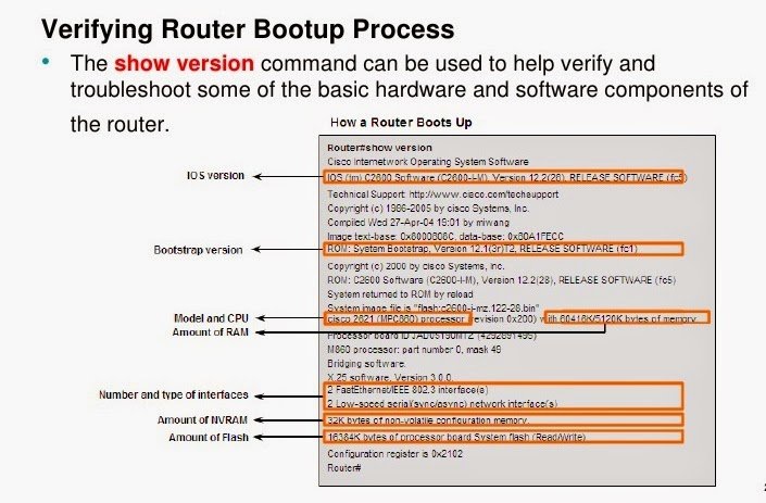
◙ Show Version - > Cisco IOS Version, Uptime Of Router, How The Router Started, Where System Was Loaded From, The Interfaces The POST Found, And The Configuration Register.
◙ Show Clock - > Shows Date And Time On Router
◙ Show History - > Shows The History Of Your Commands
◙ Show Debug - > Shows All Debugging That Is Currently Enabled
◙ No Debug All - > Turns Off All Debugging
◙ Show Users - > Shows Users Connected To Router
◙ Show Protocols - > Shows Which Protocols Are Configured
◙ Banner Motd # Your Customized Message Here # - > Set/Change Banner
◙ Hostname
PRIVILEGED MODE COMMANDS OF A ROUTER (Learn How To Work In The Privileged Mode Of A Router):
◙ Enable - > Get To Privileged Mode◙ Disable - > Get To User Mode
◙ Enable Password
◙ Enable Password
(Config-Line)#Login
(Config-Line)#Password
(Config-Line)#Login
(Config-Line)#Password
(Config-Line)#Login
(Config-Line)#Password
◙ - ➤ For More Reference - > HOW TO CONFIGURE ROUTER TELNET, CONSOLE AND AUX PORT PASSWORDS :
ROUTER PROCESSES & STATISTICS (By These Command You Can See The Statistics And Different Processes Of The Router):
◙ Show Processes - > Shows Active Processes Running On Router◙ Show Process CPU - > Shows CPU Statistics
◙ Show Mem - > Shows Memory Statistics
◙ Show Flash - > Describes The Flash Memory And Displays The Size Of Files And The Amount Of Free Flash Memory
◙ Show Buffers - > Displays Statistics For Router Buffer Pools; Shows The Size Of The Small, Middle, Big, Very Big, Large And Huge Buffers
◙ Show Stacks - > Shows Reason For Last Reboot, Monitors The Stack Use Of Processes And Interrupts Routines
IP COMMANDS(List Of The IP Commands Configure IP On An Interface):
Int Serial 0IP Address 157.89.1.3 255.255.0.0
Int Eth 0
IP Address 2008.1.1.4 255.255.255.0
OTHER IP COMMANDS:
◙ Show IP Route - > View IP Routing Table◙ IP Route
◙ IP Route 0.0.0.0 0.0.0.0
◙ IP Classless - > Use With Static Routing To Allow Packets Destined For Unrecognized Subnets To Use The Best Possible Route
◙ Show ARP - > View ARP Cache; Shows MAC Address Of Connected Routers
◙ IP Address 2.2.2.2 255.255.255.0 Secondary - > Configure A 2nd IP Address On An Interface.
◙ Show IP Protocol - > Show IP Protocol
CDP COMMANDS (CISCO DISCOVERY PROTOCOL USES LAYER 2 MULTICAST OVER A SNAP-CAPABLE LINK TO SEND DATA):
◙ Show CDP Neighbor - > Shows Directly Connected Neighbors◙ Show CDP Int - > Shows Which Interfaces Are Running CDP
◙ Show CDP Int Eth 0/0 - > Show CDP Info For Specific Interface
◙ Show CDP Entry
◙ CDP Timer 120 - > Change How Often CDP Info Is Sent (Default CDP Timer Is 60)
◙ CDP Holdtime 240 - > How Long To Wait Before Removing A CDP Neighbor (Default CDP Holdtime Is 180)
◙ Show CDP Run - > Shows If CDP Turned On
◙ No CDP Run - > Turns Off CDP For Entire Router (Global Config)
◙ No CDP Enable - > Turns Off CDP On Specific Interface
IPX COMMANDS:
◙ IPX Routing - > Enable IPX On Router. Configure IPX + IPX-RIP On An Int: Int Ser 0IPX Network 4A
OTHER COMMANDS:
◙ Show IPX Route - > Shows IPX Routing Table◙ Show IPX Int E0 - > Shows Ipx Address On Int
◙ Show IPX Servers - > Shows SAP Table
◙ Show IPX Traffic - > View Traffic Statistics
◙ Debug IPX Routing Activity - >Debugs IPS RIP Packets
◙ Debug IPX Sap - > Debugs SAP Packets
ROUTING PROTOCOLS COMMANDS (RIP, IGPR And OSPF Are The Routing Protocols And Here Is A List Of The Commands For The Working On The Routing Protocols):
CONFIGURE RIP: Router RIPNetwork 157.89.0.0
Network 208.1.1.0 OTHER RIP COMMANDS: ◙ Debug IP RIP - > View RIP Debugging Info
◙ - ➤ For More Reference- > RIP CONFIGURATION EXAMPLES:
CONFIGURE IGRP: Router IGRP 200Network 157.89.0.0
Network 208.1.1.0 OTHER IGRP COMMANDS: ◙ Debug IP IGRP Events - > View IGRP Debugging Info
◙ Debug IP IGRP Transactions - >View IGRP Debugging Info
ACCESS LISTS (List Of The Access List Command Of A Router):
◙ Show IP Int Ser 0 - > Use To View Which IP Access Lists Are Applies To Which Int◙ Show IPX Int Ser 0 - > Use To View Which IPX Access Lists Are Applies To Which Int
◙ Show Appletalk Int Ser 0 - > Use To View Which Appletalk Access Lists Are Applies To Which Int VIEW ACCESS LISTS: ◙ Show Access-Lists
◙ Show IP Access-Lists
◙ Show IPX Access-Lists
◙ Show Appletalk Access-Lists APPLY STANDARD IP ACCESS LIST TO INT ETH 0: Access-List 1 Deny 200.1.1.0 0.0.0.255
Access-List 1 Permit Any
Int Eth 0
IP Access-Group 1 In APPLY EXTENDED IP ACCESS LIST TO INT ETH 0: Access-List 100 Deny TCP Host 1.1.1.1 Host 2.2.2.2 Eq 23
Access-List 100 Deny TCP 3.3.3.0 0.0.0.255 Any Eq 80
Int Eth 0
IP Access-Group 100 Out APPLY STANDARD IPX ACCESS LIST TO INT ETH 0: Access-List 800 Deny 7a 8000
Access-List 800 Permit -1
Int Eth 0
IPX Access-Group 800 Out APPLY STANDARD IPX ACCESS LIST TO INT ETH 0: Access-List 900 Deny Sap Any 3378 -1
Access-List 900 Permit Sap Any All -1
Int Eth 0
IPX Access-Group 900 Out
WAN CONFIGURATIONS COMMANDS(Networking Over WAN Is The Main Functionality Of A Router. The Most Common Use Of A Router Is For The WAN Connectivity - List Of The Commands For The Different Methods Of The WAN Connectivity):
PPP CONFIGURATION (Point To Point Protocol Is A Method For The WAN Connectivity And You Will Find Here Some Commands Of PPP): ◙ Encapsulation PPP Authentication◙ PPP Chap Hostname
◙ PPP PAP Sent-Username
◙ Show Int Ser 0 - > Use To View Encapsulation On The Interface FRAME-RELAY CONFIGURATION (One Of The Methods For The WAN Connectivity Is The Frame Relay. Find Here Some Basic Commands For The WAN Connectivity Through Frame Relay): ◙ Encapsulation Frame-Relay Ietf - Use IETF When Setting Up A Frame-Relay Network Between A Ciscorouter And A Non-Cisco Router
◙ Frame-Relay Lmi-Type Ansi - LMI Types Are Cisco, ANSI, Q933A; Cisco Is The Default; LMI Type Is Auto-Sensed In IOS V11.2 And Up
◙ Frame-Relay Map IP 3.3.3.3 100 Broadcast - If Inverse ARP Won't Work, Map Other IP To Your DLCI # (Local) ◙ Keep Alive 10 - > Use To Set Keep Alive
◙ Show Int Ser 0 - > Use To Show DLCI, LMI, And Encapsulation Info
◙ Show Frame-Relay PVC - > Shows The Configured DLCI's; Shows PVC Traffic Stats
◙ Show Frame-Relay Map - Shows Route Mapssh Frame-Relay Lmi - > Shows LMI Info
MISCELLANEOUS COMMANDS:
◙ Show Controller T1 - > Shows Status Of T1 Lines◙ Show Controller Serial 1 - > Use To Determine If DCE Or DTE Device
◙ - ➤ For More Reference - > DTE Vs DCE:
◙ (Config-If)#Clock Rate 6400 - > Set Clock On DCE (Bits Per Second)◙ (Config-If)#Bandwidth 64 - > Set Bandwidth (Kilobits)
◙ - ➤ For More Reference - > LIST OF SHOW COMMAND REFERENCES:
PASSWORDS FOR CISCO ROUTERS AND SWITCHES
THE PASSWORDS INTRODUCED HERE ARE:
◙ - ➤ CONSOLE PASSWORD - > Limits Device Access Using The Console Connection◙ - ➤ ENABLE PASSWORD - > Limits Access To The Privileged EXEC Mode
◙ - ➤ ENABLE SECRET PASSWORD - > Encrypted, Limits Access To The Privileged EXEC Mode
◙ - ➤ VTY PASSWORD - > Limits Device Access Using Telnet
REQUIRE THAT A MINIMUM OF 10 CHARACTERS BE USED FOR ALL PASSWORDS:
◙ - ➤ Router1(Config)# Security Passwords Min-Length 10 - > Besides Setting A Minimum Length, List Other Ways To Strengthen Passwords.◙ - ➤ Router1(Config)#Enable Secret Cisco123456 - > Assign Cisco123456 As The Privileged EXEC Encrypted Password.
CONSOLE PASSWORD:
The Console Port Of A Cisco IOS Device Has Special Privileges. The Console Port Of Network Devices Must Be Secured, At A Bare Minimum, By Requiring The User To Supply A Strong Password. This Reduces The Chance Of Unauthorized Personnel Physically Plugging A Cable Into The Device And Gaining Device Access. THE FOLLOWING COMMANDS ARE USED IN GLOBAL CONFIGURATION MODE TO SET A PASSWORD FOR THE CONSOLE LINE: Switch(Config)#Line Console 0Switch(Config-Line)#Password Password
Switch(Config-Line)#Login From Global Configuration Mode, The Command Line Console 0 Is Used To Enter Line Configuration Mode For The Console. The Zero Is Used To Represent The First (And In Most Cases Only) Console Interface For A Router. The Second Command, Password Password Specifies A Password On A Line. The Login Command Configures The Router To Require Authentication Upon Login. When Login Is Enabled And A Password Set, There Will Be A Prompt To Enter A Password. Once These Three Commands Are Executed, A Password Prompt Will Appear Each Time A User Attempts To Gain Access To The Console Port. ASSIGN CISCOCONPASS AS THE CONSOLE PASSWORD, ESTABLISH A TIMEOUT,ENABLE LOGIN, AND ADD THE LOGGING SYNCHRONOUS COMMAND ( The Logging Synchronous Command Synchronizes Debug And Cisco IOS Software Output And Prevents These Messages From Interrupting Your Keyboard Input): Router1(Config)# Line Con 0
Router1(Config-Line)# Password Ciscoconpass
Router1(Config-Line)# Exec-Timeout 5 0
Router1(Config-Line)# Login
Router1(Config-Line)# Logging Synchronous
Router1(Config-Line)# Exit
Router1(Config)#
ENABLE AND ENABLE SECRET PASSWORDS:
To Provide Additional Security, Use The Enable Password Command Or The Enable Secret Command. Either Of These Commands Can Be Used To Establish Authentication Before Accessing Privileged EXEC (Enable) Mode. Always Use The Enable Secret Command, Not The Older Enable Password Command, If Possible. The Enable Secret Command Provides Greater Security Because The Password Is Encrypted. The Enable Password Command Can Be Used Only If Enable Secret Has Not Yet Been Set. The Enable Password Command Would Be Used If The Device Uses An Older Copy Of The Cisco IOS Software That Does Not Recognize The Enable Secret Command. THE FOLLOWING COMMANDS ARE USED TO SET THE PASSWORDS: ◙ - ➤ Router(Config)#Enable Passwordpassword◙ - ➤ Router(Config)#Enable Secret Password Note: If No Enable Password Or Enable Secret Password Is Set, The IOS Prevents Privileged EXEC Access From A Telnet Session. WITHOUT AN ENABLE PASSWORD HAVING BEEN SET, A TELNET SESSION WOULD APPEAR THIS WAY: Switch>Enable
% No Password Set
Switch>
VTY PASSWORD:
The VTY Lines Allow Access To A Router Via Telnet. By Default, Many Cisco Devices Support Five VTY Lines That Are Numbered 0 To 4. A Password Needs To Be Set For All Available Vty Lines. The Same Password Can Be Set For All Connections. However, It Is Often Desirable That A Unique Password Be Set For One Line To Provide A Fall-Back For Administrative Entry To The Device If The Other Connections Are In Use. THE FOLLOWING COMMANDS ARE USED TO SET A PASSWORD ON VTY LINES: Router(Config)#Line Vty 0 4Router(Config-Line)#Passwordpassword
Router(Config-Line)#Login By Default, The IOS Includes The Login Command On The VTY Lines. This Prevents Telnet Access To The Device Without First Requiring Authentication. If, By Mistake, The No Login Command Is Set, Which Removes The Requirement For Authentication, Unauthorized Persons Could Connect To The Line Using Telnet. This Would Be A Major Security Risk. ASSIGN CISCOVTYPASS AS THE VTY PASSWORD ( Establish A Timeout, Enable Login, And Add The Logging Synchronous Command): Router1(Config)# Line Vty 0 4
Router1(Config-Line)# Password Ciscovtypass
Router1(Config-Line)# Exec-Timeout 5 0
Router1(Config-Line)# Login
Router1(Config-Line)# Logging Synchronous
Router1(Config-Line)# Exit
Router1(Config)#
ENCRYPTING PASSWORD DISPLAY:
Another Useful Command Prevents Passwords From Showing Up As Plain Text When Viewing The Configuration Files. This Is The Service Password-Encryption Command. This Command Causes The Encryption Of Passwords To Occur When A Password Is Configured. The Service Password-Encryption Command Applies Weak Encryption To All Unencrypted Passwords. This Encryption Does Not Apply To Passwords As They Are Sent Over Media Only In The Configuration. The Purpose Of This Command Is To Keep Unauthorized Individuals From Viewing Passwords In The Configuration File. If You Execute The Show Running-Config Or Show Startup-Config Command Prior To The Service Password-Encryption Command Being Executed, The Unencrypted Passwords Are Visible In The Configuration Output. The Service Password-Encryption Can Then Be Executed And The Encryption Will Be Applied To The Passwords. Once The Encryption Has Been Applied, Removing The Encryption Service Does Not Reverse The Encryption. ◙ - ➤ Router1(Config)#Service Password-Encryption - > Encrypt The Clear Text Passwords.◙ - ➤ For More Reference - > HOW TO CONFIGURE ROUTER TELNET, CONSOLE AND AUX PORT PASSWORDS :
CONFIGURE THE ROUTER FOR SSH ACCESS (Enable SSH Connections And Create A User In The Local Database Of The Router):
Router1# Configure TerminalRouter1(Config)# Ip Domain-Name The School Of Cisco Networking (SCN).com
Router1(Config)# Username Admin Privilege 15 Secret Adminpass1
Router1(Config)# Line Vty 0 4
Router1(Config-Line)# Transport Input Ssh
Router1(Config-Line)# Login Local
Router1(Config-Line)# Exit
Router1(Config)# Crypto Key Generate Rsa Modulus 1024
Router1(Config)#Exit
SUMMARY OF IOS FEATURES AND COMMANDS
USER EXEC MODE:
Enable - > Enter Privileged EXEC ModePRIVILEGED EXEC MODE:
Copy Running-Config Startup-Config - > Copy The Active Configuration To NVRAM.Copy Startup-Config Running-Config - > Copy The Configuration In NVRAM To RAM.
Erase Startup-Configuration - > Erase The Configuration Located In NVRAM.
Ping IP_Address - > Ping To That Address.
Tracerouteip_Address - > Trace Each Hop To That Address. Show Interfaces - > Display Statistics For All Interfaces On A Device.
Show Clock - > Show The Time Set In The Router.
Show Version - > Display Currently Loaded IOS Version, Hardware, And Device Information.
Show Arp - > Display The ARP Table Of The Device.
Show Startup-Config - > Display The Saved Configuration Located In NVRAM.
Show Running-Config - > Display The Contents Of The Currently Running Configuration File.
Show Ip Interface - > Display IP Statistics For Interface(S) On A Router.
Configure Terminal - > Enter Terminal Configuration Mode.
TERMINAL CONFIGURATION MODE:
Hostname Hostname - > Assign A Host Name To Device.Enable Passwordpassword - > Set An Unencrypted Enable Password.
Enable Secret Password - > Set A Strongly Encrypted Enable Password.
Service Password-Encryption - > Encrypt Display Of All Passwords Except Secret.
Banner Motd# Message # - > Sets A Message-Of-The-Day Banner.
Line Console 0 - > Enter Console Line Configuration Mode.
Line VTY 0 4 - > Enter Virtual Terminal (Telnet) Line Configuration Mode.
Interface Interface_Name - > Enter Interface Configuration Mode.
LINE CONFIGURATION MODE:
Login - > Enable Password Checking At Login.Password Password - > Set Line Password.
INTERFACE CONFIGURATION MODE:
IP Addressip_Address Netmask - > Set Interface IP Address And Subnet Mask.Description Description - > Set Interface Description.
Clock Rate Value - > Set Clock Rate For DCE Device.
No Shutdown - > Set Interface To Up.
Shutdown - > Administratively Set Interface To Down.
CONCLUSION:
The Goal Of This Article Is To Give An Easy Way To Understand The “INITIAL CONFIGURATION REFERENCES OF CISCO ROUTERS AND SWITCHES: " And Also We Hope This Guide Will Help Every Beginner Who Are Going To Start Cisco Lab Practice Without Any Doubts. Some Topics That You Might Want To Pursue On Your Own That We Did Not Cover In This Article Are Listed Here! Hands - On Experience Is An Invaluable Part Of Preparing For The Lab Exam And Never Pass Up An Opportunity To Configure Or Troubleshoot A Router ( If You Have Access To Lab Facilities, Take Full Advantage Of Them) There Is No Replacement For The Experience You Can Gain From Working In A Lab, Where You Can Configure Whatever You Want To Configure And Introduce Whatever Problems You Want To Introduce, Without Risk Of Disrupting A Production Network. Thank You And Best Of LuckThis Article Written Author By: Mr. Premakumar Thevathasan - CCNA And CCNP (Routing & Switching), MCSE, MCSA, MCSA - MSG, CIW Security Analyst, CompTIA Certified A+ And Etc.
WARNING AND DISCLAIMER:
Routers Direct And Control Much Of The Data Flowing Across Computer Networks. This Guide Provides Technical Guidance Intended To Help All Network Students, Network Administrators And Security Officers Improve Of Their Demonstrated Ability To Achieve Specific objectives Within Set Timeframes. This Document Carries No Explicit Or Implied Warranty. Nor Is There Any Guarantee That The Information Contained In This Document Is Accurate. Every Effort Has Been Made To Make All Articles As Complete And As Accurate As Possible, But No Warranty Or Fitness Is Implied. It Is Offered In The Hopes Of Helping Others, But You Use It At Your Own Risk. The Author Will Not Be Liable For Any Special, Incidental, Consequential Or Indirect Any Damages Due To Loss Of Data Or Any Other Reason That Occur As A Result Of Using This Document. But No Warranty Or Fitness Is Implied. The Information Provided Is On An "As Is" Basic. All Use Is Completely At Your Own Risk.Home Page Of - > The School Of Cisco Networking (SCN) Page Of - > SCN InF4 TECH Contact Details / About Us Page To Send Email

No comments:
Post a Comment